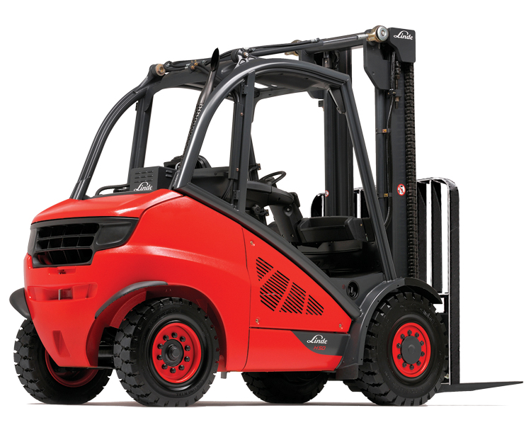
- Linde Forklift Truck H-Series Type 394-02: H40, H45, H50 Service Training (Workshop) Manual.
- Linde H120/1200, H140/1200, H160/1200, H160/600 Forklift Truck 358 series Workshop Service Manual.
Original Illustrated Factory Operating Instructions (User Manual) for Linde Diesel Forklift Truck 394-02 Series Models H40D-02, H45D-02, H50D-02.Original factory manuals for Linde Forklift Trucks, contains high quality images, diagrams and instructions to help you to operate, maintenance and repair. 394 series 2006 year. Linde 394-02 Series Diesel Truck, LPG truck, Service Manual for Linde 394-02 Series, Training Service Manual for Linde 394-02 Series. Linde 393 Forklift SeriesHere is our PDF bundle that includes the Linde 393 series forklift service manual you need (PDF formats).

This highly detailed digital repair manual covers all repairs, servicing and troubleshooting procedures. All technical details taken directly from the manufacturer can be found in this manual. Linde Forklift Truck H-Series Type 394: H40D, H40T, H45D, H45T, H50D, H50T Service Repair Manual is the same manual used by professional technicians, mechanics and workshops around the world
Linde Forklift Truck H-Series Type 394: H40D, H40T, H45D, H45T, H50D, H50T Service Repair Manual has easy-to-read text sections with top quality diagrams and instructions, will guide you through fundamentals of maintaining and repairing, step-by-step, to teach you what the factory trained technicians already know by heart, Using this repair manual is an inexpensive way to keep your vehicle working properly.
The exclusive Linde dual pedal travel control allows smooth directional changes and precise maneuvering, even in the tightest areas. A comfortable operator is a productive and safe operator. That’s why the 394-02 series is designed to the latest ergonomic standards.
Models Cover:
H40D
H40T
H45D
H45T
H50D
H50T
Manual Covers:

Contents:
0. Product information
394 truck series
Truck 394
Truck 394 MPR
Diagnostics
LHC basic structure
1. Engine
LPG engine
Description of the drive
BMFVR6 technical data
Engine block
V-ribbed belt removal and installation
Checking the compression pressure
Cylinder head removal and installation
Checking and adjusting the timing
Removing and refitting the cylinder head cover
Installing and removing camshafts
Cooling
Engine cooling system
Coolant -draining and filling
Coolant regulator housing assembly and disassembly
Engine electrics
Three-phase alternator
Electronic ignition system overview
LPG system
Safety guidelines for LPG (extract)
Basic rules when working with LPG
Sealing plastic pipe unions
Functions
LPG system -functions
Shut-down due to lack of gas
Evaporator -functions
Mixer -functions
Default settings for the LPG system
Speed control (from chassis number H2X394U04459 onwards)
LPG shut-off valve
LPG truck with a lambda control system
Exhaust gases -composition
Lambda control system
Leakage test on LPG system
LPGtank
Removing and installing the level display and 80 filling stop valve
The following safety measures must be observed
Carrying out assembly operations
Bleeding the LPG tank
The following safety measures must be observed
Procedure for bleeding
BJCdiesel engine
Description of the drive
BJC technical data
Particularities of the 1.9-litre engine
The electronic engine control unit
Sensors
Coolant temperature sending unit 0B1
Engine speed sensor 0B2
Actual speed sensor 1B1
Fuel temperature sending unit 0B3
Sensor 0B4
Needle stroke sensor 0B5
Height sensor
0B3 control gate valve travel sensor
Glow plug system
Pre-heater system
Glow plugs- engine 0R1
Fuel supply
Fuel quantity regulation
Fuel quantity actuator 0B3
Fuel shut-offvalve 0Y1
Injection timing device- replacement of O-ring on cover
Start of injectionvalve 0Y2
Start of injection -governing
Start of injection -dynamic check and adjustment
Injection nozzle -Two-spring nozzle holder
Injection nozzles- removal and installation
One-way restrictor
Injection system – overview
Injection system -supply voltage check
Injection pump – removal and refitting, Exchanging the toothed belt
Injection pump – removal and installation
Injection pump – pump and toothed belt adjustment
Engine block
Ribbed V-belt- removal and fitting
Crankshaft oil seal on pulley end -removal and installation
Crankshaft sealing flange- removal and installation
Checking the cylinder head
Cylinder head – removal and fitting
Cylinder head – compression check
Valve gear
Oil pressure and oil pressure switch -check
Oil sump – removal and installation
Checking hydraulic bucket tappets
Camshaft- removal and installation
Vacuum pump
Air volumeter 0B6
Solenoid valve for boost pressure limitation 0Y4
Charge air system with exhaust turbocharger
Cooling
Coolant -draining and filling
Coolant thermostat- removal and installation
Water pump -removal and installation
Coolant pump -Checking for wear
Engine electrics
Three-phase alternator
Replacing the engine control unit/ immobilizer
Self-diagnostics
Self-test- introduction
Self-diagnostics -troubleshooting
Standardised measured value blocks
Measured value block 01 -evaluation
Measured value block 04 -evaluation
Measured value block 05 -evaluation
Measured value block 07 -evaluation
Measured value block 10 -evaluation
Measured value block 11 -evaluation
Measured value block 12 -evaluation
Measured value block 13 -evaluation
CBJBdiesel engine (pump injection)
Description of the drive
CBJB technical data
Sensors
Checking the coolant temperature sensor 0B1
Checking the engine speed sensor 0B2
Removing and installing the engine speed sensor 0B2
Actual speed sensor 1B1
Checking the hall-effect sensor 0B8
Checking the fuel temperature sensor 0B3
Checking suction pipe temperature sensor 0B4
Checking the suction pipe pressure sensor 0B4
Glow plug system
Ceramic glow plugs 0R4
Fuel supply
Rules for working on the direct fuel injection system
Checking the tandem pump delivery pressure
Removing and installing the tandem pump
Pump injection unit- overview
Pump/nozzle unit -Checking valves 0Y2
Removing and installing the pump injection unit
Changing the O-rings and thermal protection seal on the pump injection unit ..
Engine block
Cylinder block -overview
V-ribbed belt- removal and fitting
Removing and installing the free-wheel belt pulley
Toothed belt -removal and fitting, tensioning
Changing the crankshaft sealing ring on the toothed belt pulley side
Removing and installing the crankshaft sealing flange
Cylinder head -overview
Cylinder head cover- removal and installation
Removing and installing the cylinder head
Cylinder head -checking the compression pressure
Valve train – overview
Valve stem covers- removal and installation
Valves
Checking the camshaft for axial play
Removing and installing the camshaft sealing ring
Removing and installing the camshaft
Oil filter and oil cooler -overview
Removing and installing the oil sump
Suction pipe -overview
Checking the suction pipe flap switchover
Suction pipe flap -Checking switch valve 0Y16
Vacuum hoses -connection diagram
Air volumeter 0B6
Checking the charge pressure limitation solenoid valve 0Y4
Exhaust gas recirculation
Exhaust gas recirculation -overview
Checking exhaust gas recirculation
Checking the exhaust gas recirculation valve 0Y3
Checking the mechanical exhaust gas recirculation valve
Cooling
Checking the cooling system for leaks
Draining and filling coolant
Removing and installing the coolant thermostat
Removing and installing the coolant pump
Self-diagnostics
Self-diagnostics – introduction
Error code table
Standardised measured value blocks
Measured value block 01 -fuel injection quantity
Measured value block 03 -exhaust gas recirculation
Measured value block 04 -pump/nozzle unit activation
Measured value block 07 -temperatures
Measured value block 10 -air variables
Measured value block 11 -charge pressure control
Measured value block 12 – heating status
Measured value block 13 – idling smooth running control
Measured value block 18 valve status of the pump/nozzle unit
Measured value block 23 – BIP deviation (solenoid valve switching times)
2. Gearbox
Description
Technical data for traction drive
System overview up to 06/2011
MPR system overview from 07/2011
Traction drive
Travel drive – introduction
The triplex pump
Working hydraulics pump MPR 50
MPR50 general
MPR50 overview
Hydraulic adjustment with electronic activation
Auxiliary brake valves
Auxiliary brake valve from 1 0/2006
Start of regulation of the pump
Bypass valve
Output unit
Hydraulic fan drive
Removing and installing the HPV variable displacement pump coupling flange
Hydraulic diagnostics on the truck
Overview and explanations about diagnostics
HPV 105-02 pressures -measurements
Checking the hydrostatic traction drive
Sealing the HMF 1 35 wheel motor
Wheel motor HMF 135-2, central brake sealing
Gearbox GR6H – changing the shaft seal
3. Chassis, bodywork and fittings
Chassis
Axle suspension
Instructions for working with gas springs
Driver’s seat
Driver’s seat Isringhausen
Driver’s seat controls
Service instructions
4. Chassis frame
Steering system
Steering system – functional description
Brake system
Brake release valve
Brake cable pulls – Adjusting
Checking the brake system
5. Operating devices
Accelerator
Function
Replacement
Stop screws
Joysticks
Joysticks up to 06/2011
Joystick variants
Functional description
Replacement
Joysticks from 07/2011
Joystick configurations
Joystick variants
Joystick interlock
Functional description
Exchange
6. Electrics / Electronics
General
Safety instructions for electrical equipment
EMC- Electromagnetic compatibility
CAN bus
CAN bus connection assembly X15
Electrostatic charging
Identifying components in electrical circuit diagrams
Pin assignment for the LHC 10 controller with 121 contacts
Pin assignment for the LHC 20 Tricor controller with 154 contacts
MPR plug positions
Central electrical system
Linde Truck Control (LTC/LHC)
LHC controller with ECO mode
Arrangement of the console to vehicle adaptor connectors
Arrangement of relays and fuses for basic equipment and special equipment
Display unit up to 06/2010
Display unit until 06/2010
Display unit from 07/2010
Display unit
Checks
LHC testing (truck control unit and lift control)
Testing the VW controller and immobiliser(WFS)
Checking wiring harness
Testing sensors
Testing the indicator unit
7. Hydraulic system
Working hydraulics
Function characteristics of control valve
Overview
Operating hydraulics circuit diagram
Function characteristics
Pressure relief valve
DepressurisationAuxiliary hydraulics 1and 2
Hose layout for pump control valve
Hose layout of control pressure supply
Increase of the volume flow rate – auxiliary hydraulics 1 and 2
Cleaning work on the Linde control valve -cast valve
Cleaning instructions
8. Load lift system
Lift mast
Lift mast – identification
Lift mast installation and removal
A dusting the lift chain (all series)
Setting the roller play
Roller play – fork carriage in the inner mast,family 1 89
Roller play -middle and inside mast profile, Series 189
Outer Mast Roller Clearance, Type 1 89
Removal of slide pads – standard mast
Removal of slide pads -duplex mast
Removal of slide pads – triplex mast
Lift cylinder (outer) – removal and installation
Lift cylinder (centre) – removal and installation
Lift cylinder – sealing
Setting the tilt angle transmitter
Tilt cylinders
Hose reservoir – removal, exchanging hose, sealing, fitting
9. Special equipment, accessories
Lighting
Working spotlight position
Annex
10. Circuit diagrams
Hydraulic circuit diagrams
File Format: PDF, 606 Pages
Compatible: All Versions of Windows & Mac
Language: English
Requirements: Adobe PDF Reader & WinZip
Q. Can I use this Manual on more than one computer?
A. Yes, this Manual can be used on as many computers as required.
Linde 394 Service Manual

Q. Can I print out a page?
A. Yes you can print out a single page or the entire manual, its your choice.

Q. Is this a trial or a limited version?
A. No, this is the FULL Manual without any limitations or trial periods and can be used for life.
Q. Will this PDF Manual work on Windows & MAC computers?
A. Yes, it is fully compatible with all Windows & All MAC Computers.
After your payment, you will have instant access to your download. We will always try to get the full satisfaction of our customers. Even after you have purchased this manual, we will pay full attention to any issues, regardless of the nature of the situation.
THE DOWNLOAD LINK WILL ALSO BE SENT TO YOUR E-MAIL.
Linde 394 Series Service Manuals
So please make sure your email address is correct. Don’t Forget to Check Spam / Junk if can’t find the new message in your email inbox immediately.
Linde 394 Series Service Manual User
Thanks for visiting!